Week 4: Embedded programming
Summary of the Week
This week's focus was on programming a microcontroller. The individual assignment was to read a microcontroller datasheet and program a board to do something, using at least two different development workflows. The group assignment was to compare the performance and development workflows for different microcontroller architectures.
⭐ Group Assignment
Our full group documentation, where we compare different microcontrollers and their development environments, can be found on our group assignment page.
Comparing Workflows: MicroPython vs. Arduino
For our group assignment, we compared two main programming approaches: MicroPython and the Arduino (C/C++) framework.
- MicroPython: We found this to be a simple, high-level language. Its best feature is being real-time and interactive. Using an IDE like Thonny, we could connect and read sensor data instantly in the shell without recompiling. The drawback is that it's interpreted, making it less efficient.
- Arduino (C/C++): This framework uses a compiled language, making it much faster and more efficient. The trade-off is that it's not interactive. To get a sensor reading, you must write, compile, and upload the entire program, which is a slower development cycle.
In short, we found a clear trade-off: MicroPython is superior for rapid testing and real-time data, while Arduino is the better choice when final performance and speed are the priority.
🚀 Individual Assignment: Programming My Board
For my individual assignment, I will be programming the XIAO ESP32-C3 board, which features the ESP32-C3 microcontroller from Espressif. I will first simulate the task on Wokwi to see how it works, and then I will implement it on the actual hardware using two different workflows: the Arduino IDE and python on thonny.
Step 1: Reading the Datasheet
The first step was to understand the board and its microcontroller. The XIAO ESP32-C3 uses the ESP32-C3FN4 chip from Espressif. This is a 32-bit RISC-V single-core processor, which is a significant step up from the 8-bit AVR chips. The official datasheet (PDF) documents the ESP32-C3, ESP32-C3FH4, and ESP32-C3FN4 variants together, since they share the same pin layout and core specifications.
Key Chip Specifications (ESP32-C3)
| Feature | Specification |
|---|---|
| CPU | RISC-V 32-bit single-core |
| Max Frequency | 160 MHz |
| On-Chip Memory | 400 KB SRAM + 4 MB Flash |
| Wireless | 2.4GHz Wi-Fi (802.11 b/g/n) and Bluetooth 5 (LE) |
| GPIOs | Up to 22 (11 available on the XIAO) |
| Interfaces | I2C, I2S, SPI, UART, ADC |
| Operating Voltage | 3.3V |
XIAO ESP32-C3 Pinout
The most critical information for programming is the pinout. I needed to map the physical pins on the tiny XIAO board to their GPIO (General Purpose Input/Output) numbers and their names in the Arduino IDE.
.png)
Image source: Seeed Studio XIAO ESP32-C3 Wiki, licensed under CC BY 4.0.
| XIAO Pin | Arduino Name | GPIO Number | Functions |
|---|---|---|---|
| D0 | `D0` / `A0` | GPIO2 | ADC1_CH2, UART1_TXD |
| D1 | `D1` / `A1` | GPIO3 | ADC1_CH3 |
| D2 | `D2` / `A2` | GPIO4 | ADC1_CH4, I2C SDA |
| D3 | `D3` / `A3` | GPIO5 | ADC1_CH5, I2C SCL |
| D4 | `D4` | GPIO6 | SPI_CLK |
| D5 | `D5` | GPIO7 | SPI_MISO |
| D6 | `D6` | GPIO21 | UART0_TX (Serial) |
| D7 | `D7` | GPIO20 | UART0_RX (Serial) |
| D8 | `D8` | GPIO8 | SPI_MOSI, BOOT Button |
| D9 | `D9` | GPIO9 | SPI_CS |
| D10 | `D10` | GPIO10 | SPI_HD |
| LED | (No Arduino Name) | GPIO8 | Onboard User LED (Blue) |
Step 2: Wokwi simulations
Before working on the actual hardware, I simulated my program on Wokwi, a free online simulator for Arduino, ESP32, and other embedded boards that lets you build and test circuits in the browser before touching real hardware.
I started off simple by first just connecting a push button with an Led and trying to simulate that. I connected the led cathode to ground and the anode to a resistor and pin 9. The button to ground and pin 8. Here I encountered an error because in the code I had actually used pin 9 for the button and pin 8 for the led. However, there were a few errors first this was not the xiao c3 and moreover the pin 8 was occupied by the board for on board LED which caused nothing to happen once the button was pressed.
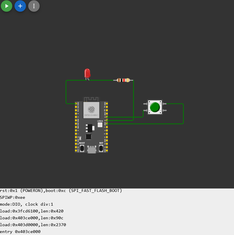
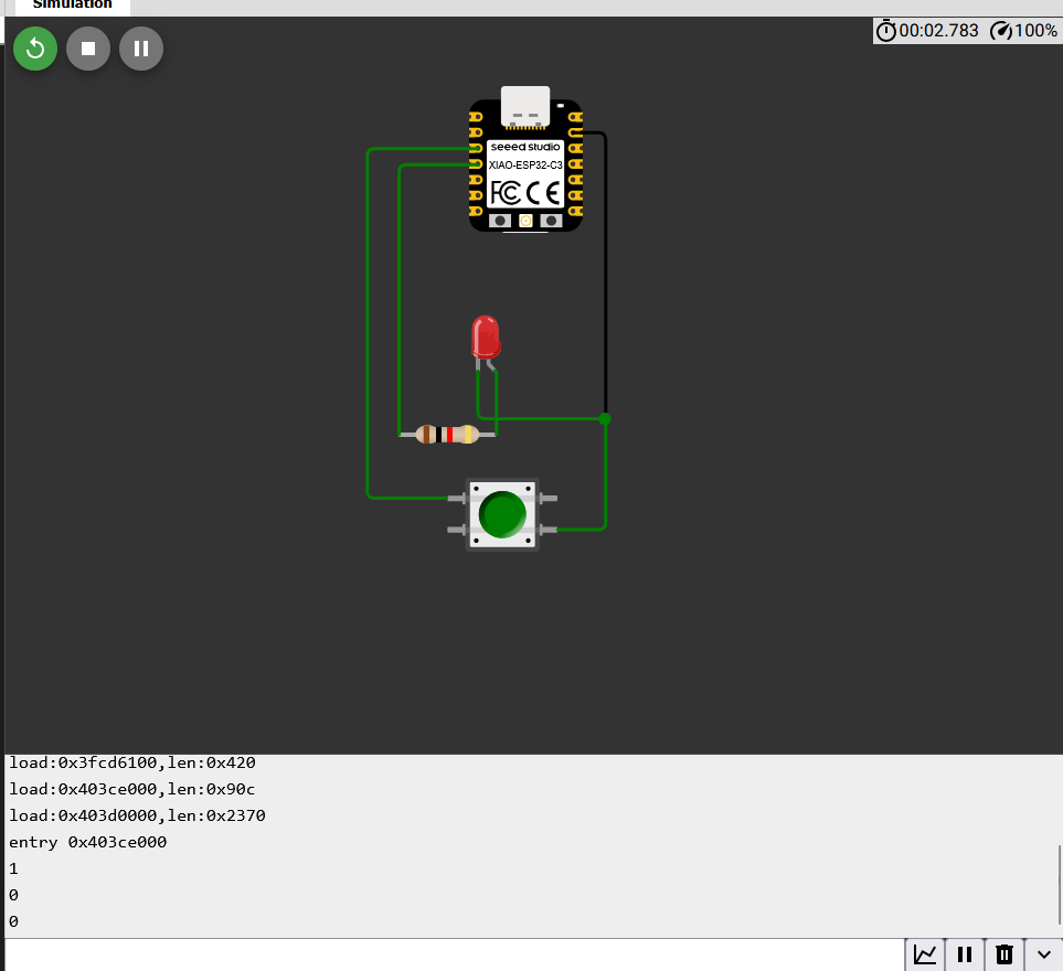
First I changed the board to the xiao ESP32-C3 then wrote the code again and did the wiring. However, I didn't assign D to the pin numbers becasue of which the code didn't work and I spent quite a lot of time changing the circuit and then finally when i added the D to make it D2 and D3 it finally worked. After fixing the pin numbers I was able to get the led to turn off when the button was pressed. Here is the wokwi project.
One important detail here is the use of INPUT_PULLUP when setting the button's pin mode. The ESP32-C3's GPIO pins float (give unpredictable readings) when nothing is connected to them. By calling pinMode(buttonPin, INPUT_PULLUP), the chip's internal pull-up resistor holds the pin at a stable HIGH (3.3V) when the button is open. Pressing the button connects the pin directly to ground, pulling it LOW. This means the button reads HIGH when it is not pressed and LOW when it is pressed, the inverse of what you might expect, but it avoids needing an external pull-up resistor and prevents the erratic floating-pin readings you'd otherwise get.
Here is the final code I used for the simulation:
const int buttonPin = D2;  // pushbutton pin
const int ledPin = D3;     // LED pin

int buttonState = HIGH;    // matches the resting (unpressed) state with INPUT_PULLUP

void setup() {
  Serial.begin(115200);

  // enable internal pull-up resistor
  pinMode(buttonPin, INPUT_PULLUP);

  // LED output
  pinMode(ledPin, OUTPUT);
}

void loop() {
  // read the state of the pushbutton (LOW = pressed, HIGH = not pressed)
  buttonState = digitalRead(buttonPin);
  Serial.println(buttonState);

  // button pressed?
  if (buttonState == HIGH) {   // not pressed
    digitalWrite(ledPin, HIGH);  // turn LED on
  } else {                      // pressed
    digitalWrite(ledPin, LOW);   // turn LED off
  }
  delay(1000);
}
Here is what diagram looked like:
Step 3: Arduino
After successfully simulating the program on Wokwi, I moved on to implementing it on the actual XIAO ESP32-C3 hardware on breadboard using the Arduino IDE.I first downloaded the Arduino IDE from the offical website and then downloaded the esp32 board support package from the board manager which took some time to install. The wiring was the same as in the simulation: the button connected to pin D2 and ground, and the LED connected to pin D3 with a current-limiting resistor to ground. I used male to male jumper cables to connect everything with the GND to the breadboard ground rails and the rest as before.
This is what the circuit looked like:
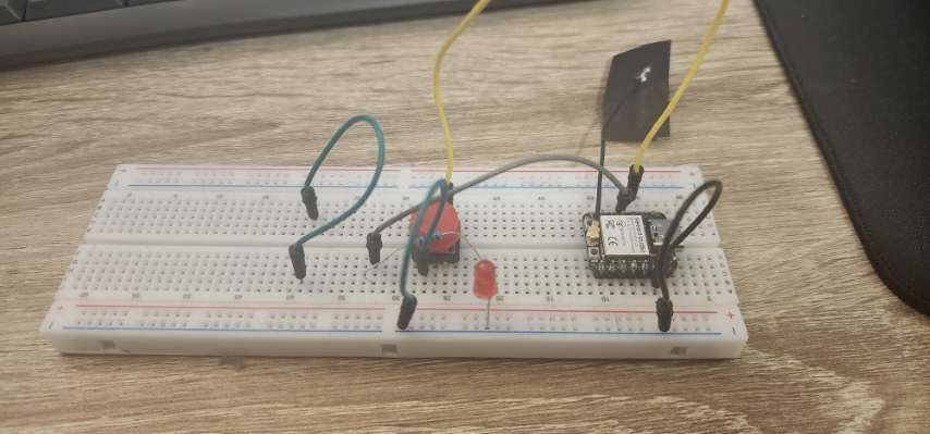
The code is the same as above and I uploaded it to the board and it worked perfectly. When I pressed the button, the LED turned off, and when I released it, the LED turned back on. I also monitored the serial output to see the button state being printed every second.
Here is a video of the setup in action:
Here is a picture of the serial monitor showing the button state:
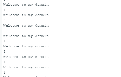
As you can see the button state is printed as 1 when the button is not pressed and 0 when it is pressed, which confirms that the program is working as expected.
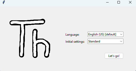
Step 4: MicroPython with Thonny
To satisfy the requirement of using two different workflows, I decided to recreate the exact same physical circuit using MicroPython. For this, I used Thonny, which is an excellent beginner-friendly Python IDE designed specifically for microcontrollers.
Flashing the Firmware
Unlike Arduino, which compiles the C++ code and flashes it directly to the board, MicroPython requires an interpreter to be installed on the microcontroller first.
- I went to the official MicroPython website and downloaded the latest stable `.bin` firmware file for the ESP32-C3.
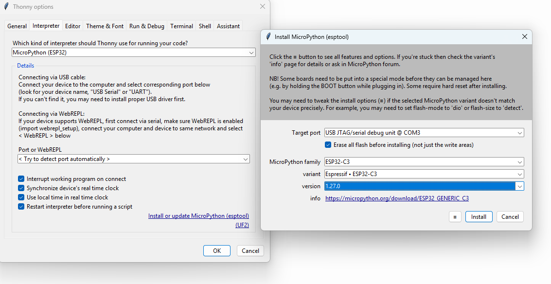
- In Thonny, I went to Run > Configure interpreter, selected "MicroPython (ESP32)", and selected the COM port for my XIAO.
- I clicked "Install or update MicroPython", selected the `.bin` file I downloaded, and flashed the board.
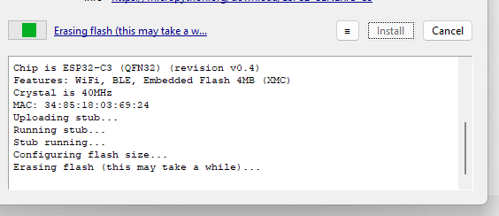
Here is the flashing process in action:
Writing the Code
A major difference I discovered between the Arduino workflow and MicroPython is how pins are addressed. In Arduino, I used the aliases D2 and D3. However, in MicroPython, you must address the pins by their actual hardware GPIO numbers. Looking back at my datasheet table in Step 1, I saw that D2 maps to GPIO4 and D3 maps to GPIO5.
Here is the MicroPython code to replicate the button and LED logic:
from machine import Pin
import time

# Initialize pins using actual GPIO numbers
# D2 is GPIO4 (Button), D3 is GPIO5 (LED)
button = Pin(4, Pin.IN, Pin.PULL_UP)
led = Pin(5, Pin.OUT)

print("Starting MicroPython Button Test...")

while True:
    # Read button state (1 = unpressed, 0 = pressed due to PULL_UP)
    button_state = button.value()
    print("Button State:", button_state)

    if button_state == 1:
        led.value(1)  # Turn LED on when not pressed
    else:
        led.value(0)  # Turn LED off when pressed

    time.sleep(1) # Delay to match the Arduino sketch
Testing the Output
One of the massive advantages of MicroPython is the REPL (Read-Eval-Print Loop). As soon as I clicked the "Run" button in Thonny, the code executed immediately without needing to wait for a compiler. I could see the print() statements updating live in the Thonny shell at the bottom of the screen.
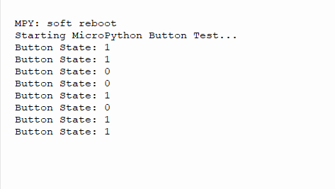
The physical hardware reacted exactly as it did in the Arduino test, successfully proving the second workflow!
In conclusion, this week was a fantastic learning experience. I got to explore the differences between two major programming workflows for microcontrollers and successfully implemented the same functionality using both Arduino and MicroPython. The interactive nature of MicroPython was particularly impressive, allowing for rapid testing and debugging without the need for a compile-upload cycle.
Download Files
 ← Back to Main Page